Mayfly
comad September 4th, 2015
Special thanks to Leif Ohlsson for permission to use extracts from his Mayfly project website.
Leif Ohlsson
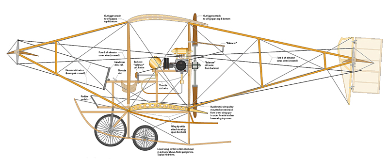
The control system worked out by Lilian Bland was advanced and ingenious; in places quite difficult to understand due to its complexity. It combined elevators and ailerons in a way that today would be called “elevons”. The two front elevators could be worked together as pure elevators by pulling or pushing on the handlebar.
If you turned the handlebar left or right, the elevators would deflect in different directions, one side up and one side down. To accomplish this, the elevator control wires running from the bottom bellcrank of the handlebar were crossed.
The front elevators, in turn, were coupled to the moving sections of the rear stabilizers, also with crossed wires, so that when you pulled on the handlebar the front elevators went “up” and the rear ones “down’; working together to make the machine’s nose turn upwards. It should be noted that the aileron and the elevator functions of front and rear elevators were coupled, so that both functions could be activated by, e.g., pushing and turning the handlebar at the same time. The ordinary aft rudder was actuated by foot pedals.
In addition, there was a backrest control, so that if the pilot leaned left in response to an imbalance towards the right, the “balancer” between the wings on the right side (what we today would call aileron) was pulled down to make the right wing rise and the machine level out. According to the practice of the era, these ailerons hung down when the machine was at rest on the ground, while the airflow in flight would keep them horizontal until one of them was pulled down by leaning left or right.
The entire control system demonstrates the degree to which Lilian Bland had studied the various approaches taken by airplane designers of her day , and fruitfully applied them to her own machine. The exact running of some of the many control wires required, remains conjectural due to the difficulty of interpreting existing photos. The same goes for many pulleys and fittings which have been deduced. As an example, the drawing represents a best guess for how the rudder wires from the foot pedals, and the “balancer” (aileron) wires ran.
Leif Ohlsson
THE “MAYFLY” GETS ITS ENGINE.
[Letter to “Flight” magazine from Lilian Bland, published July 16th, 1910]
I have at last got my engine. To hasten matters, I went over to England and brought it back not quite under my arm, but on two spars; it fitted very neatly into a railway carriage and also on to an outside car.
I got it on the aeroplane and tried it late last night; but as I have not got my tank yet I tried to feed it out of a whisky bottle, and the only tubing I could find was my aunt’s ear-trumpet. Under the circumstances the engine behaved better than I expected, it was like a cat-fight on a very enlarged scale.
The natives, I hear, thought one of the mills had blown up, but as the noise continued they put it down to a thunderstorm; in the meantime I found the mechanic, while deeply interested in the engine, was liberally pouring the petrol over the main plane instead of down the ear-trumpet, and the engine subsided with a sigh. As it was pouring with rain and too dark to see, the proceedings were terminated and I think I will wait for the tank, and as the engine is English, its sense of humour is not developed sufficiently for these proceedings.
Leif Ohlsson
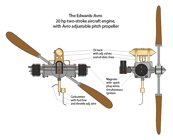
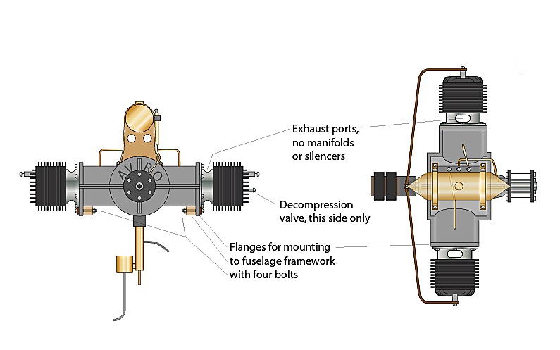
The engine drawing represents the particular engine & prop Lilian Bland personally brought home to Ireland from the factory in England. It is based entirely on the few photos available, and many features remain conjectural.
Leif Ohlsson
Lilian Bland’s own comments on her flying machine
[As published in Flight, DECEMBER 17, 1910, pp 1025-27, Global Fight Archive pdf-files 1910 ,1027-29, slightly abridged, edited, and commented in places]
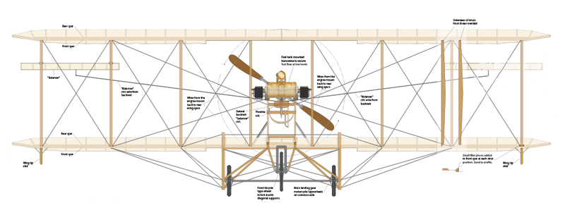
“The engine bed is a separate chassis set across the main spars to which it is clipped; stays run from the rear spar to the chassis, which is also wired out to the upper and lower spars. Carries the tank and the pilot’s seat, the latter being slung by four straps. In front, the bar for the elevator control. The whole chassis can be removed in one piece either with or without the engine, which is held in place by four bolts.
“The controls consist of a bicycle handlebar which rocks and turns. Turning the handle to the right raises the right hand elevator and depresses the left, the connecting wires being crossed. The elevators are connected to the horizontal tail planes, which work in the opposite direction to the elevators; all controls are double, wire and strong waterproofed whipcord.
“The balancing planes, which are hinged to the rear stanchions, are controlled by the back of the seat, leaning to the right pulls down the right hand balancer and vice versa. The vertical rudder is worked by pedals.
[The way Lilian Bland had rigged her control system is somewhat different compared to later convention. In response to the aircraft banking (leaning) to the right, she would turn the handlebar in the same direction to correct it. It would have been easy to rig the aircraft more intuitively, like when you ride a bicycle – just crossing the top wires from the handlebar, instead of the lower pair, would produce a left bank by turning the handlebar left. Lilian Bland’s way of rigging the controls therefore must have been a conscious choice, and the drawing shows her original rigging. The way the backrest control is described, on the other hand, appears to contain a mistake (at least the way it is printed in Flight magazine ):
Leaning to the right will pull down the left balancer (not the right), thus banking the aircraft towards the right. To sum up the way her system worked:
Pushing on the left handle and leaning left at the same time would produce aleft bank.]
“The engine controls consist of a butterfly valve which regulates the petrol supply, an air throttle, and a lever to the magneto, while when starting one cylinder is cut out.
“When the engine starts the draught from the propeller lifts the tail and the tip of the skids off the ground, and the machine balances on the two wheels; the third wheel in front only comes into action over rough ground, and the purpose is to prevent the machine from going on to her nose; it answers admirably.
“The construction of the machine is more or less of the usual type, but the trailing edge and wing tips are more flexible. Originally steamed ribs were used, but were later discarded, as they did not keep their proper curve ; the present ribs are cut out solid to the correct curve for the lower surface of the rib, and are given a flatter curve on the top, while they are bored out for the sake of lightness.
[The comment about the wing profile is difficult to interpret. The wing profile as drawn here is just a best guess.]
“The tank and carburettor float are placed across the span of the machine,so that the fore and aft tilt does not interfere with the petrol supply when the tank is getting empty; tanks are made now with two cocks leading to the tube, which gets over this difficulty where the fuel is fed by gravity.”
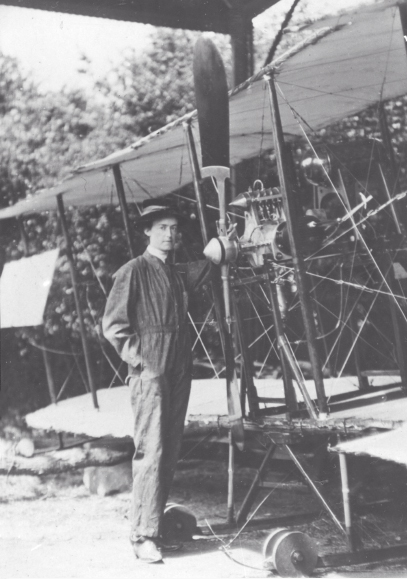
Lilian and Mayfly
Excerpts from her letter to Flight magazine July 16th 1910.
I find mechanic’s overalls are the best things to wear; skirts are out of the question with all the wires, etc., not to speak of oil.
The boxwood wheels on end of skids are only for running the machine along the road. The motor is a 20hp Avro, and the propeller an Avro, adjustable pitch, 6 ft. 6 in. (1.98m) diameter; the engine is beautifully balanced, but all the same the vibration is enormous, and I find that all the nuts dance themselves loose; however, I can double-nut most of the bolts. I had the engine running nicely on Saturday, and as soon as I have got everything so that it will not shift, I shall take the machine up to the flying ground I have been lent. It is a fine place, 800 acres, but it also contains a loose bull, and if it gets annoyed and charges I shall have every inducement to fly!
This page has the following sub pages.
- Comments(0)